6.1 Analysis Preparation - How it Works
- MacSlope can prepare and calculate thousands of trial slip surfaces in a single analysis. The following is brief overview of how it works.
Generating the Slip Surfaces
- When using a search grid, circles are drawn from each search grid point intersecting the top surface of the drawing geometry at the specified Slip Entry Interval. Slip surfaces must pass through Ranges, when defined.
- Circles must intersect the top surface of the drawing geometry at least once.
- Circles may intersect the top surface of the drawing geometry such that 2 or more distinct soil mass segments are created. Each segment will be analyzed separately.
- Circles that intersect the top surface of the drawing geometry an odd number of times will attempt to have a valid segment analyzed following the rule depicted and described below:
- Where circles intersect an impenetrable region, the slip surface follows the top of the impenetrable region for the intersected portion of the circle, or until the slip surface daylights the drawing geometry top surface.
- Circle intersections with the drawing bottom boundary are treated as though they have intersected an impenetrable region, as above.
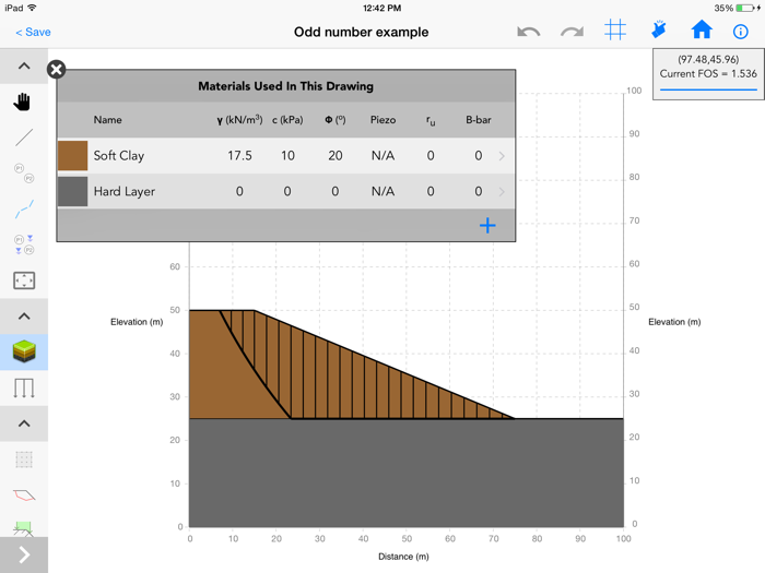
Valid Slip Surface - Circle intersects top surface once and daylights top surface along hard layer
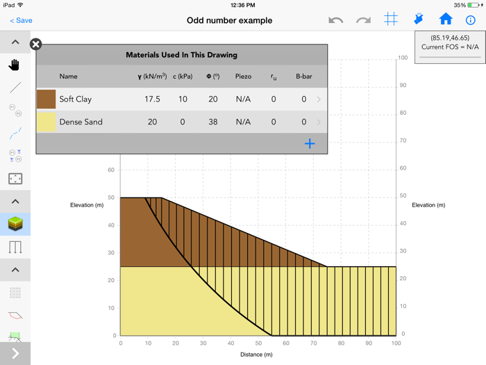
Invalid Slip Surface - Circle intersects top surface once and daylights through drawing side boundary, trial is removed
- When using Specified Surfaces, the slip surface is defined by the user. However, the above points regarding left/right boundaries, distinct soil masses, and impenetrable regions still apply.
Slice Discretrization
- Once the shape and extent of the trial slip surface is known, it is discretized into slices as follows:
- First, slice boundaries are added where the trial slip surface intersects the top surface, defining the trial segment.
- Second, a slice boundary is added below the slip center, if within the segment boundaries.
- Third, slice boundaries are added at intersection points of the slip surface with lines, piezo lines, and tension crack zones.
- Fourth, slice boundaries are added where any defined surcharges begin and end.
- Fifth, slice boundaries are added at any line or piezo line end points within the trial segment. This is to avoid slope breaks in the geometry from occuring within a slice.
- Finally, slice boundaries are added to meet the Maximum Slice Width criteria specified in Analysis Settings.
- Once slices have been discretized and created for the trial slip surfaces, slices may need to be removed as follows:
- Where trial slip surfaced intersect No Strength Regions, slices are removed if they contain only no strength materials. This results in a vertical slip surface through no strength materials.
- Where trial slip surfaces intersect Tension Crack Zones, slices are removed to the depth of the tension crack.