3.3 Points, Lines, and Regions
Points and Lines
- Points and lines form the basis of the drawing geometry.
- Select the Line Tool
 in the tool palette, or select Line Tool from the Drawing Menu.
- Click and move your cursor inside the drawing bounds to create lines and form the regions of your desired geometry.
- Lines drawn with the line tool will snap according to the snap preferences. It is helpful to have snap-to-points enabled for connecting line end points, and snap-to-lines enabled when drawing a line that intersects an existing line.
- When a line is drawn that intersects an existing line, the target line is split and a new point created there.
- Points common to multiple lines are automatically merged.
- MacSlope automatically detects the lines forming the top ground surface of the drawing and draws them in bold.
- The Point Editor pane is displayed to the right of the drawing. It contains a list of all the points that make up the lines in the drawing geometry.
- Click the Edit Points
 button in the Point Editor Pane to edit the point geometry.
- You will be presented with a point marker
 for each point in the drawing geometry.
- Click a point distance or elevation coordinate in the table to edit it.
- Drag a point marker to graphically move the point. It will snap according to the snap preferences. Points that are common to multiple lines will move together.
- Double click on a point's distance or elevation coordinate in the table to edit it with text input.
- Click the Draw Lines button in the Point Editor pane to draw line geometry using the Line Tool.
Import Point Geometry
- Click the Import Geometry button in the Point Editor Pane to import point geometry from a .csv file, or from the clipboard (ie. copy and paste).
- The .csv file containing the point geometry must contain only 2 columns - distance and elevation. When the points are imported, line segments are created between points in the order they are provided.
- When importing from the clipboard, copy 2 columns of distance-elevation coordinates from a typical spreadsheet application. Line segments are created between points in the order they are provided.
Using the Select/Pan Tool to modify lines
- Select the Select/Pan Tool
 in the tool palette, or select Select/Pan Tool under the Drawing Menu.
- Click once on a line in the drawing geometry to select it. Red circles will be displayed at the line end points to indicate it is selected. Now right click over the selected line and a menu will be presented with the following options:
- Add Point: Add's a point to the line at the location where you pressed.
- Show/Hide Slope Angle: Displays the slope angle of the line.
- Set/Reset Slip Layer: Modifies a subsurface line to act as a thin seam of the specified material. See Slip Layers.
- Set Tension Crack Zone: Modifies a surface line to have a tension crack zone to the specified depth below it. See Tension Cracks.
- Trim Line: Trims the segment of the selected line to the nearest line intersection from where you pressed. Creates a new point at the trimmed location.
- Delete: Delete's the line from the drawing. Alternatively, a selected line may be removed from the drawing by pressing the delete (⌫) key.
Regions
- Regions are automatically detected by MacSlope as areas that are enclosed by lines.
- Select the Select/Pan Tool in the tool palette, or select Select/Pan Tool under the Drawing Menu.
- Click inside a region to select it. The region will turn red to indicated it is selected. Now right click inside of the region to fill it with a material from the drawing or from the material library.
- Right clicking over the region again allows you to change the material or empty the region.
- There can not be "empty" regions prior to running an analysis. (ie. all regions must be filled with a material)
- If a line is drawn through an existing region with the Line Tool , the region is emptied and you will have to reset the region materials.
Other Considerations for Slope Geometry
- It is recommended to draw slope geometry that extends well past the crest and toe of the slope, to ensure that slip surfaces starting or kicking up farther away from the slope crest or toe, are analyzed.
- It is recommended to extend the drawing bottom well past the depth of the slip surfaces of interest. Slip surfaces that intersect the drawing bottom boundary will follow the bottom boundary and may result in unintended factors of safety being calculated.
- Lines that do not connect to another line with both ends (ie. dangling) are not allowed in the drawing prior to running an analysis. Similarly, lines that do not connect to any other lines (ie. stray) are not allowed in the drawing prior to running an analysis.
- It is recommended to have a geometry point at every intersection between lines. (ie. do not leave lines "crossing" with no common intersection point)
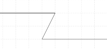
- The top surface of the slope geometry can not contain any "overhanging" lines, as depicted below (vertical slopes are acceptable):